Project 3P, Part 19: Wiring Vintage Cibie Type 95I Driving Lights (Fiat 128 3P Restoration)


Yes. I agree. We are getting a little ahead of ourselves; installing accessories does, more often than not, come towards the completion end of a project. However, I'd generously been given a set of vintage Cibie 95I driving lights - last fitted to mate Mark Drury's long-gone '70s Mitsubishi Lancer hatchback - and was looking for an excuse to muck about with P3P.
Luckily, thirty five-plus years in a box had been kind to the lights, which came with clear, chip-free lenses, almost completely unblemished reflectors, perfect plastic cases and two pristine black covers with Cibie logos printed in a chrome finish. I guess this shouldn't be a surprise, though; Mark's training as an architect clearly informs his almost archival approach to storage.


FIRST THINGS FIRST: GETTING THE LIGHTS WORKING ...
The thing is, one of the lights didn't work and a faulty bulb wasn't to blame. Closer inspection revealed that organised and dry as Mark's cache may have been, the alloy rivets that connected the external terminals to the internal wiring had oxidised enough that they wouldn't carry current.
 |
| Above and below: the corroded rivets. |

This was rectified easily enough. First, a very fine hole - 2.5 mm, from memory - was drilled through the centres of each rivet, leaving their outers in place and not affecting their strength.


Two small steel screws were then screwed into the drilled holes, from the back of the light, protruding just far enough inside that their tips were visible within the rivets' concave faces. These faces and the attached wires were then lightly sanded to expose shiny metal, over which two inelegant but effective gobs of solder were applied, fusing the screws, rivets and wires together, restoring current flow.
 |
| Screw tips visible in the centre of each rivet. |
 |
| Not the prettiest soldering ever! Effective, though! |
 |
| Both sides of each exterior terminal were cleaned up, too. |
STUFF THAT WAS NEEDED …
Any electrical installation's going to require wire (cable), crimp terminals, a fuse, a switch and - for heavier duty applications, like driving lights - a relay. Cable ties, conduit and insulating electrical tape's handy, too. Care needs to be taken to ensure that the current-carrying components are up to spec or there's a very real danger that the whole lot will overheat and might even catch fire!
To be honest, I always forget the formula for working out the appropriate amperage for wire, fuses and relays. However, my basic understanding is that a car's voltage (most being 12 volts) and the output of the accessories being powered (2 x 55 watt lights, for a total of 110 watts in this case) determines the amperage of the componentry required.
The link below explains this in detail and with actual authority, so I strongly suggest that you familiarise yourself with its contents before embarking on your own wiring job!
And because I'm a dysnumerate git, here's the simple online calculator that I use so that you can confidently select components appropriate to your own specific application:
PS: I always "round-up" or slightly over-spec all the stuff that I use, anyway.
MOUNTING THE RELAY AND CONNECTING IT TO POWER ...
It'd be nice to think that wiring in a set of driving lights to a basic mid-70s Fiat would be simple. But it's not. In fact, it's a proper pain in the arse!
Why … ?
1/. being an Aussie car - ie: right hand drive - the battery's in the diagonally opposite corner to the driving position, meaning that cabling has to run the length of two sides of the engine compartment. (If it were left hand drive, it would only need to run up one side and through the firewall, where it'd be nice and close to all the other switches and controls.)
2/. There's bugger all space to mount a relay on the passenger's side and, even if there were, it's a long, l o n g way to run the switch wires back to. And I've already used the best option on that side to mount a fan override relay, as explained here: https://uppermiddlepetrolhead.blogspot.com/2022/08/project-3p-part-18-custom-built.html.
3/. There are hardly any existing grommets on the firewall through which wires can be conveniently routed into the cabin. Not on the driver's side, at least. This isn't insurmountable, of course; there are always work-arounds but that doesn't mean that they're necessarily straightforward. More of this later ... .
Anyway ...
The relay was mounted on the driver's side of the engine bay, between the radiator expansion bottle and a relay or regulator of some sort. Doing this first seemed to make sense, as the relay is sort of like the wiring hub, handling all the electrical inputs and outputs. There was also a handily placed bolt in that location, making the mounting very simple. I then just worked outwards from the relay.

 |
| Relay wiring: blue - from battery (pin 30); yellow - from switch (pin 86); black - to earth (ground / pin 85); green - one to each light (pins 87 & 87A). Please also refer to the diagram below. |


A 10 amp wire was connected to pin 30 of the relay, then routed downwards and along the front of the car, cable tied to a loom running below the radiator to the passengers' side and up to the positive terminal of the battery. An inline 10 amp fuse was added on the inner side of the driver's mudguard, placed for easy access in case it ever blew.
 | ||
The thinner of the two blue cables connects the + terminal of the battery to pin 30 of the relay. I don't, but probably should, follow a more standard colour scheme. The fused red & black wire powers the fan override.
|

FITTING A SWITCH AND TAPPING INTO A LOW CURRENT POWER SOURCE …
A switch wire was fed from pin 86 on the relay, in behind the heater core, through a firewall grommet - for the heater / demister / fresh air box flaps, I think - then up under the dash to one of three terminals on the switch. A second wire was then added to one of the remaining two terminals (no logic here; just trial and error) and was piggy-backed onto the green and black high-beam indicator light wire behind the instrument cluster (the low current power source to activate the relay).
 |
| Above and below: the yellow switch wire encased in a protective plastic tube running behind the heater box, en route to the heater control cable grommet near the centre of the firewall. |

 |
| This is the open area behind the instrument binnacle, accessible by removing two screws and disconnecting the speedo drive and two loom connecting blocks. The switch wire is yellow. |
 |
| Yellow switch wires from the high-beam indicator light and back to pin 86 of the relay. |
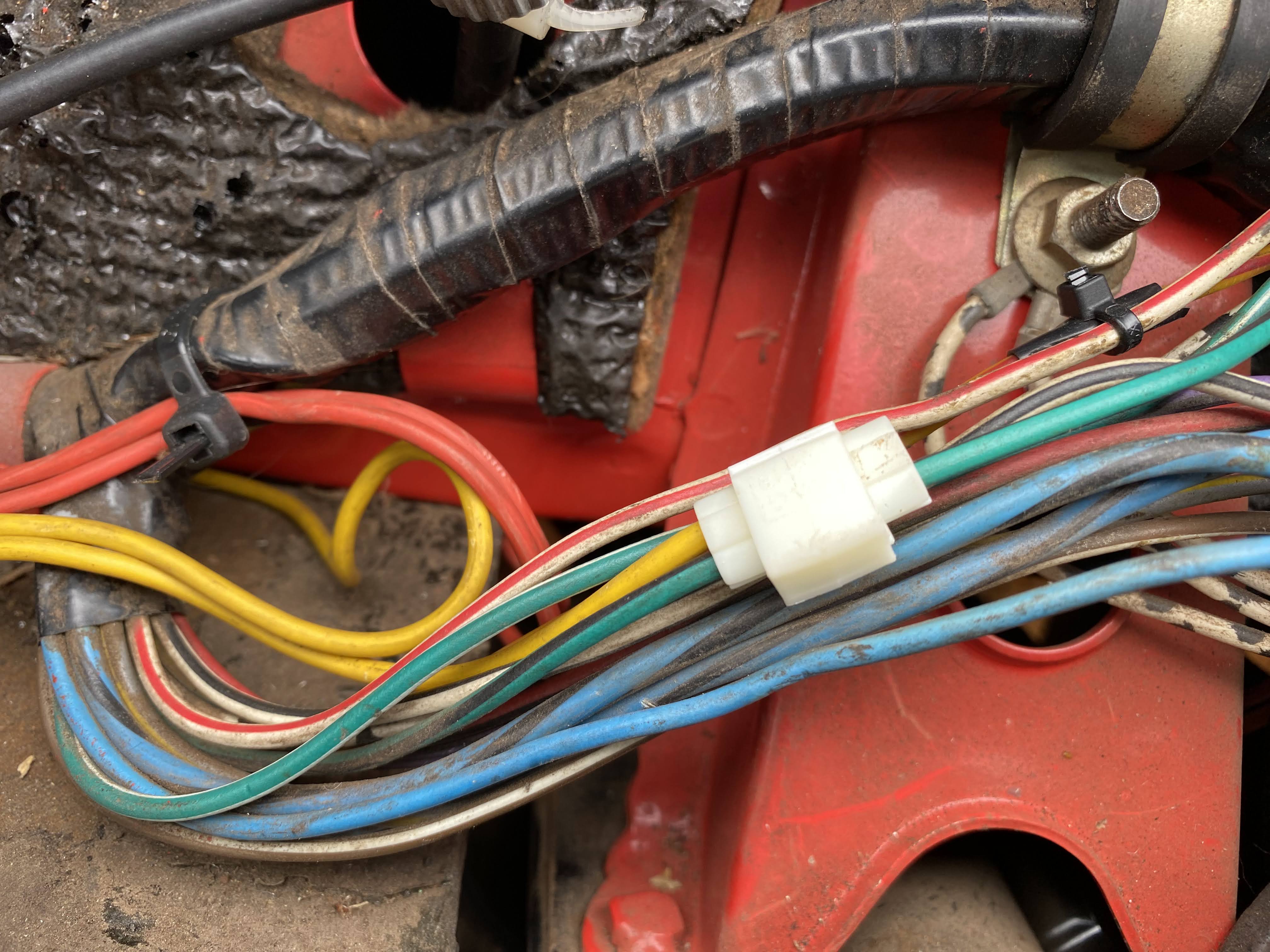 |
| Yellow switch feed piggy-backed off the green and black high beam-indicator light wire, via the white plastic block just to the RHS of the photo's centre. |
 |
| Repurposed X1/9 demister switch (RHS) slotted perfectly into an original 128 blanking panel - one of the joys of "parts bin" componentry. Gauges test-fitted only. Their installation will be described in Part 20, once the job's been completed and written up. |
Getting the switch wire up under the dash to the switch necessitated dropping the cowl on which the choke, hand-throttle, fan and demister switches, and temperature / air-direction levers are mounted, and that hides the heating system’s innards. Once opened, access is reasonably good; there's sufficient room to get your hand inside and enough structures to cable tie the wire to.
 |
| The area to the RHS and below the interior light is the cowl. Removing it is straightforward; once it's open, there's enough room to ferret about inside and to route the switch wires. |
CONNECTING THE ALL IMPORTANT EARTH WIRE …
Next, a short black earth wire was taken from pin 85 and grounded on the bolt securing the relay in place. This was the only connection that didn't require the combined skills of a needle-threader and a contortionist.
AND, FINALLY, THE LIGHTS …
Two further wires - both green - were run from pins 87 and 87A, along the inner panel below the radiator and connected to the driving lights' positive pins. Their negative pins were then wired to earth via the underside of the bumper, using the same bolts that mounted the lights themselves. (Luckily for me, my second hand bumper came pre-drilled for ancillary lights.)
All the wires were secured by the liberal use of cable ties. If there was any risk of them chafing on anything, conduit or clear plastic tubing was employed to reduce the risk of short circuits occurring.
 |
| Plastic tubing protecting one of the wires to the lights, where it exits the engine bay, alongside the driver's side bumper bracket. |
 |
| Underside of bumper showing green input (+) and blue earth wire (-). |
 |
| They work! |
That's it! They're wired in and they work. Not rocket science, I admit, but hopefully useful info for someone.
Did you enjoy this piece? If so, why not check out P3P, Parts 1 - 18, or even consider following Upper Middle Petrol Head?
Cheers,
U M P H
(uppermiddlepetrolhead.blogspot.com.au.)
iPhone images.


An exceptionally engaging piece that blends technical accuracy with real-world practicality. Its clarity, depth, and professional insight make it an essential read for anyone aiming to expand their expertise and strengthen their technical understanding.
ReplyDeleteCable Ties